GUIDE TO EV MOTOR CONTROLLER OPERATION & FEATURES (PART-1)
The surge in Electric Vehicles (EVs) demand has been remarkable across the globe. The term Electric Vehicle is not a recent advancement in the automobile industry. Electric or Battery-operated Vehicles were invented utilized even before gasoline-powered vehicles became the norm. But the technology never gained traction due to multiple factors including inefficient powertrain, sub-standard battery technology, range anxiety, and significant development strides in the combustion engine technology coupled with improvements in production processes that made them affordable.
Fast forward, General Motors launched EV1 in the 1990s that met with unprecedented success. This led several OEMs to venture into this space including the pioneers such as Toyota and Tesla, with remaining OEMs joining the bandwagon gradually. The re-emergence of EVs can be attributed to multiple factors including the development of Li-Ion Battery technology for addressing Energy Density & Range Anxiety along with evolution in Motor design, architecture & production operations.
But as Motors and Battery evolved, pioneers and early proponents felt a simultaneous need to develop motion control mechanisms and solid-state electronics for better efficiency during the conversion of electric power. The field of Power Electronics and Embedded systems also transitioned to meet the rugged and dynamic requirements during a vehicle operation. Such a developmental synergy in the field of motion control, power conversion, and embedded electronics led to the advent of Motor Controllers, also known as Motor Control Units (MCUs) or Traction Inverters.
MOTOR CONTROLLER
Motor Control Unit (MCU) is an electronic module that interfaces between the batteries and motor to control the electric vehicle’s speed and acceleration based on throttle input. The controller transforms the battery’s direct current into alternating current and regulates the energy flow from the battery. The controller also reverses the motor rotation during regen which in turn charges the battery.
Motor Controllers intended for EV application can be broadly classified into following categories: Voltage, Power & Current. The table below summarizes such specifications for different vehicle class.
MOTOR CONTROLLER SPECIFICATIONS, BY VEHICLE CLASS
| Vehicle Class | Rated Voltage (Vdc) | Rated Current (Arms) | Peak Current (Arms) | Peak Power (kW) |
| 48/72 | 30~110 | 100~320 | 1.5~5 | |
| 48/72 | 110~200 | 320~400 | 7~10 | |
| 48/72/144 | 150~250 | 350~500 | 10~30 | |
| 336 | 75~200 | 150~400 | 30~100 | |
| 540 | 200~400 | 300~700 | 150~300 |
SOURCE: Sterling Gtake E-Mobility Ltd. Analysis
NEED FOR EFFICIENT MOTOR CONTROLLER
- Motor Output: 2*π* RPM*Torque
- Torque: Torque Magnetic Flux*Input Current
Efficiency of Motor can be increased either by altering Input Current or Flux to have better resulting Torque. But modifying these parameters affect the size of motor which is governed by EV space and weight. Therefore, design of an efficient controller becomes of paramount importance.
MOTOR CONTROLLER OPERATION
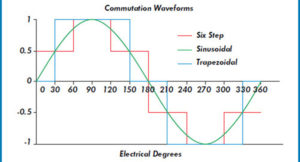
Following Control Logic modes have been used for motor commutation:
- Trapezoidal
- Modified Trapezoidal or ‘Six-Step’
- Sinusoidal
Trapezoidal control, although easy to implement produced significant torque ripples at each commutation step and thereby, hampering efficiency.
The Torque output of a motor is maximized when the stator & rotor magnetic fields are at 90°. With Sinusoidal control, each of the motor winding getting current with a phase difference of 120° & the result is a smoothly rotating current vector with a constant magnitude that is orthogonal to the rotor. This results in the elimination of torque ripples that translate into smooth motion and precise motor control.
SOURCE: MotionControl Tips
But as the motor speed increases, efficiency deteriorates due to an increase in frequency of sinusoidal current signals which makes it difficult for motor controllers to track. Additionally, due to an increase in the speed, frequency, and amplitude of back-emf also increase, further hampering the motor efficiency. As a result, Sinusoidal Control is utilized for low-cost Brushless DC Motor Controllers integrated in Low-Speed Electric 2-Wheelers. For application beyond Low-Speed Vehicles, Field Oriented Control (FOC) is further deployed to align stator current orthogonal to rotor flux. Over the past few years, the cost for processing technology used in FOC has reduced, thereby, making FOC commercially viable for High-Speed Electric 2-Wheelers and 3-Wheelers.
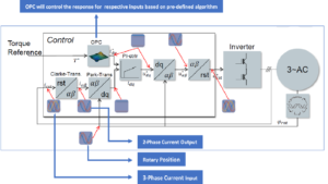
FIELD ORIENTED CONTROL (FOC)
While sinusoidal control is based on three-phase system dependent on time & speed, under Field Oriented Control (FOC), this three-phase system is converted two coordinate system- ‘d’ (aligned with flux component) and ‘q’ (aligned with current/torque component).
In principle, Clark transform is utilized to convert current in three-phases into two-phase (axis) waveforms with same amplitude. Next, Park transform converts two-axis system from a fixed reference to a rotating frame of reference synchronized with rotor flux. The resulting ‘d’ & ‘q’ values are orthogonal to each other with ‘q’ being the axis current producing the required torque. As the ‘q’ value increases, the torque gets increased correspondingly.
Further, a PI Controller is used for each ‘d’ & ‘q’ to read current error signals while amplifying them to produce the required voltage in the motor. As voltage is produced on a rotating frame of reference, an inverse Park transform converts it to a stationary frame of reference which finally undergoes inverse Clark transform for converting the two-axis voltage into a three-phase voltage for each motor winding.