
FIELD ORIENTED CONTROL (FOC) ALGORITHM FOR MOTOR CONTROL
Motor Control is a mixture of lot of engineering domains together and that’s what makes it even more interesting. You need to know how a motor works, what are the algorithms and the principles behind the motor controller. Knowledge of microcontrollers is needed for development of firmware. Motor control can also be studied using model-based design in tools like MATLAB/Simulink.
A motor controller as a product involves Embedded programming, power electronics and control systems. You can’t run a motor efficiently if you do not know your control system well.
Finally, we must deal with mechanical stuff and thermal design. It’s a topic which most people avoid during design phase, but it would be a huge mistake to avoid it.
Motor control is a vast subject and gives ample opportunity to innovate. It’s a great opportunity to learn so many engineering fields in one application.
Motors are used in a lot of different applications. In a robotic arm, aim is to control the position of the arm, in case of a washing machine, control over the speed of the motor is required, whereas in electric vehicles, control over the torque of the motor to accelerate or slow down the vehicle is required.
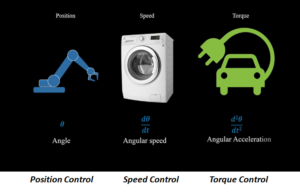
Torque is directly proportional to the current flowing in the motor. More the current flowing in the windings of the motor, higher will be the torque.
In Electric Vehicle there is a battery pack which is a DC source. As the DC voltage can’t be fed directly to the windings of 3 phase motor. DC power must be converted to three phase AC power. This is where Field Oriented Control (FOC) help us.
In FOC, it is possible to control the current to feed the windings via throttle/accelerator. More the throttle is applied, higher is the current flowing through the windings and consequently higher is the torque.
An FOC algorithm involves 3 basic steps:
- Read current sensor value (feedback current) and read the applied throttle (reference current).
- Find the error between the two values.
- Send error to the PI block which generates the voltage signal which is sent to the inverter.
- Repeat all steps at high sampling frequency.
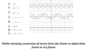
In FOC, 3 phase time varying sinusoidal currents can be controlled by converting them into 2 axis system using Clarke Transform. This 2-axis system is referred to as Stationary reference frame.
![]()
Though 3 (a, b, c) vectors have been reduced to 2(α, β) vectors, these AC quantities are difficult to control as compared to DC ones. This problem is solved using Park Transform, it helps to transform stationary reference frame vectors into rotating reference frame (d, q) . The d-q frame is rotating with the rotor flux.
Maximum torque is produced when angle between stator flux vector and rotor flux vector is 90 degrees.
The q axis component controls the torque of the motor, and the d axis component controls the flux. Since these are dc quantities, they can be controlled in an easier way in control system as compared to time varying sinusoidal components.
![]()
Software flow:
Step1: Read phase currents using ADC.
Ia = ADC_Channel_1 – OFFSET
Ib = ADC_Channel_2 – OFFSET
Ic = 0 – Ia – Ib
Step2: Convert Iabc into Iαβ using Clarke transform.
I (α, β) = I (a, b, c)
Step3: Calculate angle (θ)
Calculate angle between rotor flux vector/d axis and α axis using position encoder, hall sensor, resolver.
Step4: Convert Iαβ to Idq using Park transform.
I(d,q) = I (α, β, θ)
Step5: Pass arguments in PI loop to generate voltage signals.
Vd = PI (Id_ref, Id)
For PMSM, Id_ref = 0, since it has a permanent magnet, we need not provide any flux current.
Vq = PI (Iq_ref, Iq)
Iq_ref is referred to as torque desired, it comes from throttle/ accelerator.
Step6: Convert Vdq into Vαβ using inverse park transform.
V (d,q) = V (α, β, θ)
Step7: Convert Vαβ into Vabc using inverse clarke transform.
V (a, b, c) = V (α, β)
Step8: Convert Vabc into PWM signals using Sine Wave Modulation (SPWM) or Space Vector Modulation (SVM).
PWM (A, B, C) = SVM (V(a,b,c)) OR SPWM(V(a,b,c))
Note: Step1 to Step 8 should be executed at a frequency of about 15-20 KHz
Field oriented control is the most efficient way to drive electrical motors. One characteristic of FOC algorithm which makes it different from conventional motor control strategies like Sinewave Commutation or Trapezoidal Commutation is its ability to control phase currents being supplied to motor in real time. It allows electric motors to operate smoothly over the entire speed range and has ability to generate full torque at zero speed.